EVS Powers
1 / 5
Features with the following specifications:
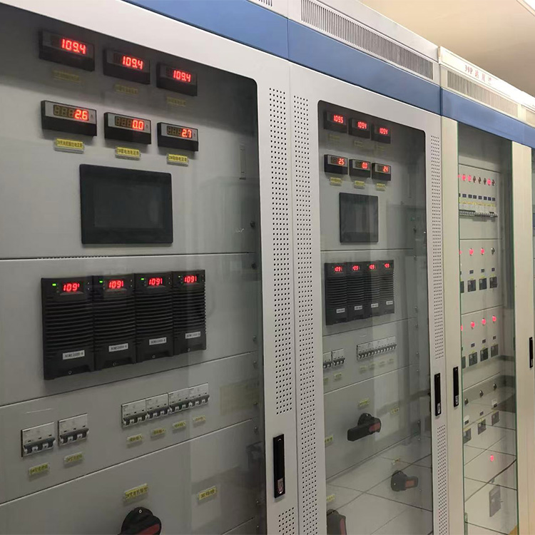
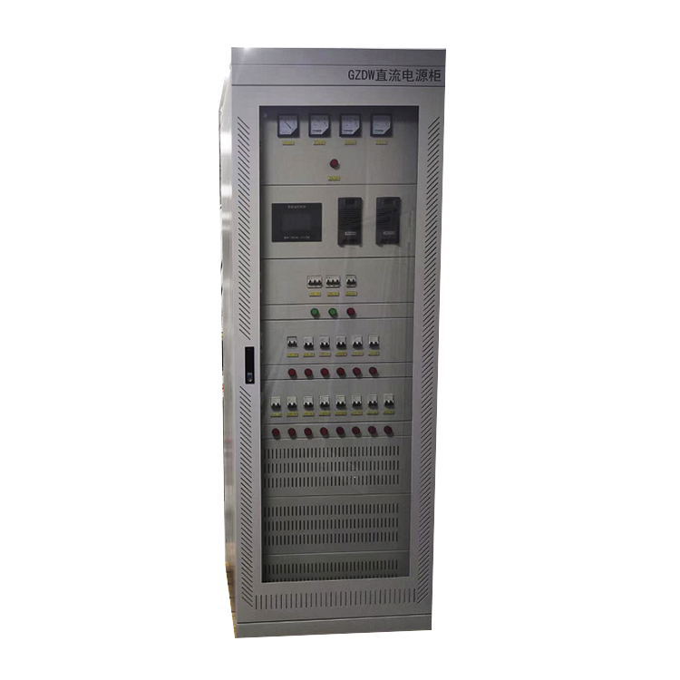
Currently, power operating power supplies in power plants and substations all use DC power. DC power supply panels provide power to control loads, power loads, and DC emergency lighting loads, forming the foundation of modern power system control and protection. The development of modern science and technology, especially computer and communication technologies, is driving power systems towards integrated automation, unmanned substations, and networked centralized management. As a crucial component of the power system, the DC power supply system (DC panel) needs further improvement in power quality, reliability, and automation levels, thus requiring the application of numerous advanced technologies.
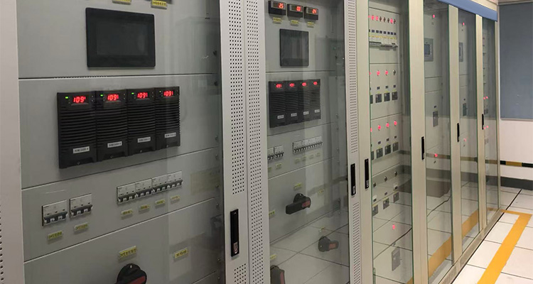
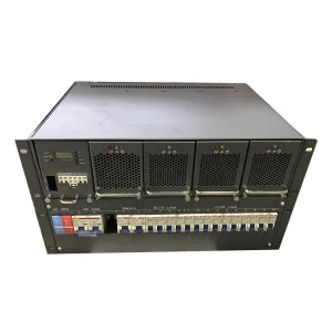
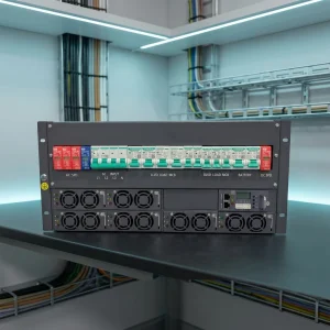
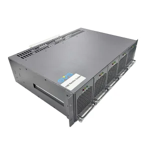
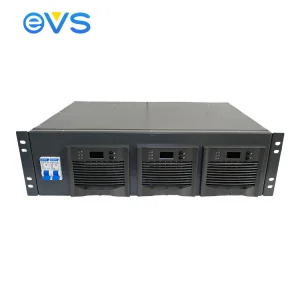
A direct-current switchgear assembly (DC power supply complete switchgear) consists of one or more low-voltage switchgear, converters, float chargers, and related control, measurement, signaling, protection, and regulation units. The manufacturer is responsible for completing all internal electrical and mechanical connections, assembling the entire assembly using structural components.
It mainly comprises the power input system (AC input), dual-path power transfer system, charger control system, charger, DC distribution system, insulation monitoring system, integrated controller (the system monitoring and control system, the brain of the DC power supply), flashing system, communication system, and battery. Among these, the integrated controller, dual-path power transfer, charger control, and charger selection are key aspects ensuring the reliability of the DC power supply.
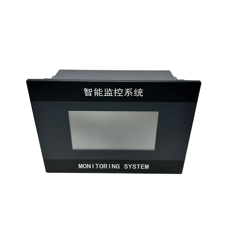
The integrated controller is responsible for monitoring the operation of the DC power supply; that is, it must have a complete understanding of every aspect of the DC power supply's operation and ensure the system operates at its optimal state. Its controlled battery monitoring unit provides voltage monitoring for each battery cell, enabling early detection of battery deterioration and timely battery replacement. This prevents catastrophic consequences such as the system's inability to provide DC power in the event of a power outage due to battery problems.
The insulation monitoring system protects the DC power supply from damage caused by external devices or system grounding. The appropriate battery configuration and selection ensure normal system operation during power outages and prevent power interruptions due to damage to the DC power supply itself.
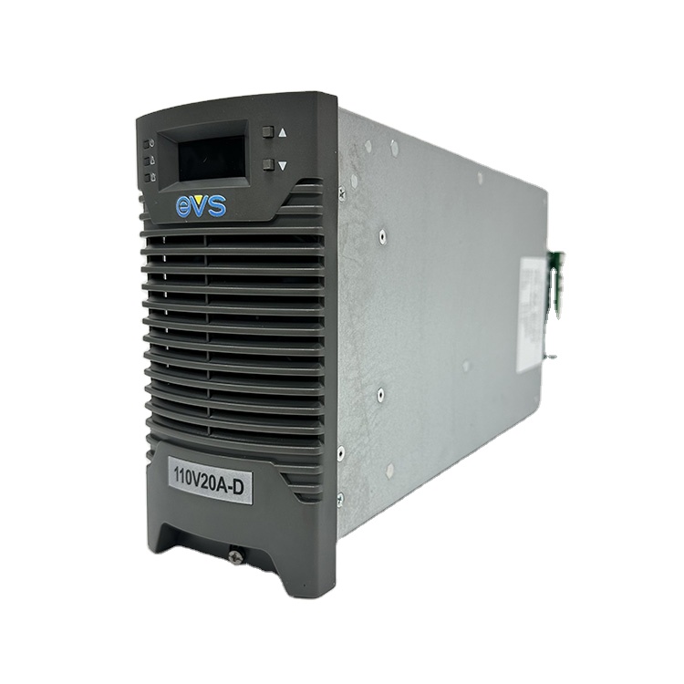
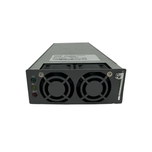
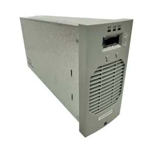
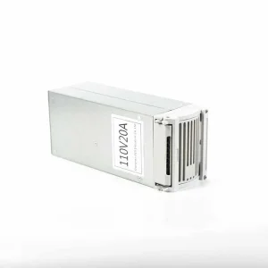
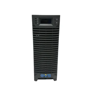
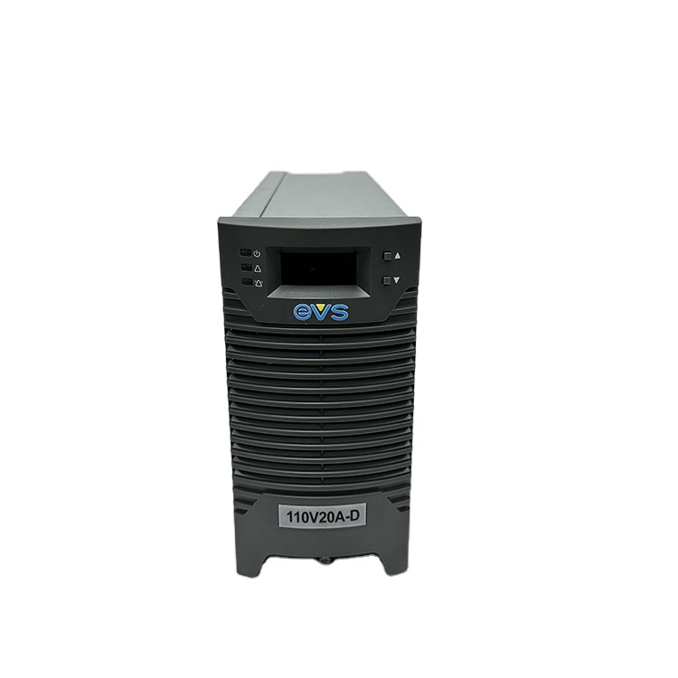
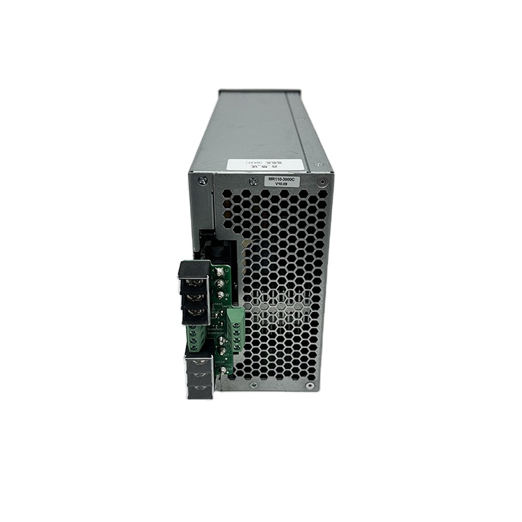
Chargers typically use dedicated high-frequency switching power supply modules. Their user-friendly design simplifies system design, offers excellent reliability, and is reasonably priced. DC power supplies of 110V 65Ah and below generally use the EVS11020 dedicated high-frequency switching power supply module; while DC power supplies above 110V 65Ah mostly use EVSPOWER products.
The communication system can provide the host computer with detailed information on the operation of the DC power supply and can also provide local and remote alarm functions. In addition, a microcomputer insulation monitoring unit can be selected according to the user's requirements to realize the low current insulation monitoring of the feeder branch.
| Item | Index | Test Condition | ||
|---|---|---|---|---|
| Minimum Value | Typical Value | Maximum Value | ||
| Input voltage range (VAC) | 300 | 380 | 485 | Output 240VDC, full load |
| Output adjustable range (VDC) | 176 | 230 | 300 | Input 380VAC, full load |
| Stabilized voltage precision | - | 0.01% | 0.5% | Output 198~286VDC, 20~100% load, input 300~485VAC |
| Stabilized current precision | - | 0.08% | 0.5% | Output 198~286VDC, 20~100% load, input 300~485VAC |
| Dynamic response | 100uS | 150uS | 200uS | Rated output 20~75% load jumps |
| Charging efficiency | 90% | 92% | 93% | Output 240V, 5A, 10A, 20A |
| Maximum audible noise (dB) | - | 45 | 50 | Full load, environmental noise 40dB |
| Storage temperature (℃) | -40 | 25 | 60 | - |
| Working environment temperature (℃) | -10 | 25 | 45 | Output 240V, 5A, 10A, 20A |
| Broadband noise (mV) | 18 | 25 | 40 | Rated input and output, resistive load |
| Peak-to-peak noise (mV) | 100 | 300 | 400 | Rated input and output, resistive load |
| Un-equalizing current degree of parallel machine | ±0.5% | ±2% | ±5% | Rated input and output, monitor equilibrium flow |
| Start-up delay (s) | 3 | 5 | 8 | - |
| Ripple factor | 0.01%~0.1% | 0~20MHz bandwidth | ||
| Dielectric strength | 2000VAC 50Hz | Time is 1 minute, leak current is 10mA | ||
| Load grade | Grade I (100%) rated output current works continuously | In the range of float charging voltage | ||
| Automatic current limiting characteristic | The output current exceeds 110% of rated current | For the constant power protection, the output current shall not increase, and DC voltage shall drop | ||
| Input overvoltage/low-voltage protection | The module is with overvoltage/low-voltage input protection function. When the input voltage is less than 313±10Vac or greater than 485±10Vac, the module shall protect, no DC output, and the protection indicator light (yellow) shall be on. | After restoring the voltage to 335±10Vac~460±15Vac, the module shall work automatically. | ||
| Input phase loss protection | When the input is lack of phase, the module shall limit the power output. When the output voltage is 260V, 5A current is output. | After fault clearance, it shall work automatically and normally | ||
| Output overvoltage protection | The output shall stop automatically if the output voltage is more than 293±6VDC, in case of damaging the equipment | The module cannot recover automatically, switch on the module again after switching off it. | ||
| Output low-voltage alarm | When the output voltage is less than 198±1Vdc, the module shall alarm, there is DC output, and the protection indicator light (yellow) shall be on. | After the voltage is recovered, the module output low-voltage alarm shall disappear. | ||
| Output short circuit retraction function | When the module output is short out, the output current should not be greater than 40% of rated current. | After fault clearance, it shall work automatically and normally | ||
| Over-temperature protection | If the temperature inside the module is higher than the set value, the module over-temperature protection function shall start, the protection indicator light (yellow) of the module panel shall be on, and the module has no voltage output. | After the abnormal condition is removed and the temperature inside the module is normal, the module shall work automatically and normally | ||